Euro-SiBRAM’2002 Prague, June 24 to 26, 2002, Czech Republic
Session 9
Reliability assessment of a beam according to SBRA method and Eurocode
Abstract
The following study demonstrates on concrete example the potential of SBRA method in reliability analysis of single supported steel beam with overhanging end. The calculation is compared with the calculation according to new European codes – Eurocodes.
Key Words: SBRA method, Eurocode, Partial Factor Design, Limit State Design, random variable, bounded histogram, carrying capacity, serviceability.
Most of today’s codes for building structures design are based on semi-probabilistic „Partial Factor Design“ method. This method was developed in time of primitive computational tools and from the viewpoint of contemporary designers is excessively simplified. This method is also implemented into new european codes – Eurocodes. Adopted simplifications not allow consistent reliability assessment of structures.
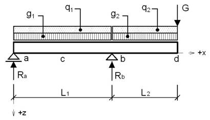
Fig. 1 Scheme of simply supported steel beam with overhanging end
Available computer technology and development in reliability theory allow to consider about the transition to fully probabilistic methods of structures reliability assessment. One of these new methods is SBRA (Simulation-Based Realiability Assessment) method, documented by Marek et. al (see [1], [2] and [3]).
The following study demonstrates the reliability assessment of simply supported steel beam with overhanging end. The study compares two completely different approaches of building structure design – approach according to Eurocodes and SBRA method (see [11]).
The goal of the study is reliability assessment of simply supported steel beam with overhanging end (see Fig. 1). The beam is made of steel rolled shape IPE 360 (steel S235). Modulus of elasticity is considered by the value E = 210 GPa. Beam span is L1 = 4,5 m and length of overhanging end is L2 = 3 m. The beam is exposed to two uniformly distributed dead loads g1 = g2 = 15 kN/m, two uniformly imposed loads q1 = q2 = 9 kN/m (office‘s areas – according to Eurocode - the category B) and force representing dead load G = 6 kN. Considered load values represent characteristic (nominal) values of these loads (see chapter 4). The beam is prevented from the lateral and torsional stability loss. The reliability assessment has be performed for carrying capacity (safety) limit state and serviceability limit state. For reliability assessment have be used the approaches based on:
1. Eurocode and
2. probabilistic method SBRA
In probabilistic analysis has be used the target probability Pd corresponding to usual level of reliability according to the Czech national code ČSN 73 1401 (see [8]).
All loads acting on the structure are in approach based on probabilistic method SBRA considered as random variable. Variabilities of these loads in the time are described by „Load Duration Curves“ and corresponding bounded histograms (see [1], [2] or [3]). All other considered random variable quantities (such as steel yield stress, structure dimensions, etc.) are described by bounded histograms. Probability of failure is determined using direct Monte Carlo simulations from the analysis of load effects combination and corresponding reference function. Determination of internal forces is based on general assumptions of statically determined bar structures, (see [10]). The calculation according to Eurocode is based on codes [5], [6] and [7].
In reliability analysis according to Eurocode are used the design values of loads given by equation (6.1a) [5]:
![]() ,
(1)
,
(1)
where
![]() is
partial load factor and
is
partial load factor and
![]() is
representative (characteristic) load value calculated from equation
(6.1b) [5]:
is
representative (characteristic) load value calculated from equation
(6.1b) [5]:
![]() ,
(2)
,
(2)
where
![]() is
combination factor and
is
combination factor and
![]() is
characteristic load value.
is
characteristic load value.
Values of load and combination factors applied in the calculation are intruduced below in corresponding chapters.
Load calculation
according to SBRA method is based on the product of maximum load
value
![]() and
random variable represented by corresponding bounded histogram
and
random variable represented by corresponding bounded histogram
![]() :
:
![]() (3)
(3)
Due to the possibility
of comparison of resulting values calculated according to Eurocode
and SBRA method, is in case of SBRA method the maximum value
![]() in
equation (3) calculated as product of nominal (characteristic) load
value
in
equation (3) calculated as product of nominal (characteristic) load
value
![]() and
partial load factor
and
partial load factor
![]() (both
these values are considered in same way as in calculation according
to Eurocode). Thus, the equation (3) can be expressed by the
following:
(both
these values are considered in same way as in calculation according
to Eurocode). Thus, the equation (3) can be expressed by the
following:
![]() (4)
(4)
Nominal (characteristic) load values and corresponding bounded histograms of loads applied in calculation according to SBRA method are shown in Tab. 1. Applied bounded histograms of loads are shown in Fig. 2.
Tab. 1 Nominal values and corresponding bounded histograms of loads
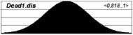
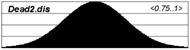
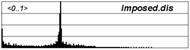
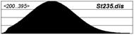
Fig. 2 Applied bounded histograms of random variable input quantities
The calculation according to Eurocode is based on so-called „design situations“. The Eurocode [5] distinguishes four design situations. In each of them can be applied various limit states. This Eurocode distinguishes two main limit state group – carrying capacity limit state and serviceability limit state. For corresponding design situations and corresponding limit states must be determined critical load situations, which represents compatible combinations of various load effects expressed i.e. by stress, deformation or acceleration. Critical load situations are determined using combination formulas (see EN 1990 [5]– chapters 6.4 and 6.5).
Probabilistic method SBRA is based on limit state philosophy. In reliability assessment according to this method can be applied carrying capacity, serviceability and durability limit states. In reliability analysis using SBRA method the all input random variables, described by bounded histograms, are analyzed in time due to the direct Monte Carlo simulation technique. This approach leads to direct determination of probability of failure Pf.
Equilibrium criterion is based on stability of beam position check – it is necessary to verify the possibility of lifting of the beam in support (a) and subsequent inadmissible rotation of the beam about support (b) – see Fig. 1.
Reliability assessment according to Eurocode is based on reliability criterion check:
![]() ,
(N) (5)
,
(N) (5)
where Ed
is resulting design load effect, Ed,stb are
individual stabilizing design load effects and Ed,dst
are individual destabilizing design load effects. Resulting design
load effect is in this study represented by the reaction
![]() in
support (a) - see Fig. 1. Determination of maximum design load effect
in
support (a) - see Fig. 1. Determination of maximum design load effect
![]() is
based on combination formula (6.10) according to EN 1990 [5], which
is used to determination of critical load situations. The critical
load situation and corresponding reliability factors, related to
static equilibrium check, are shown in Tab. 2.
is
based on combination formula (6.10) according to EN 1990 [5], which
is used to determination of critical load situations. The critical
load situation and corresponding reliability factors, related to
static equilibrium check, are shown in Tab. 2.
Tab. 2 Critical load situation and corresponding reliability factors
![]()
Reliability assessment according to SBRA method is based on analysis of reliability function given by equation:
![]() ,
(N) (6)
,
(N) (6)
where E is
resulting load effect corresponding to target probability of failure
Pd. Resulting load effect
![]() is
represented by reaction
is
represented by reaction
![]() in
support (a).
in
support (a).
The calculation of reaction
![]() performed
by computer program AntHill for Windows (see [3]) is shown in Fig. 3.
The calculation corresponds to the 100000 simulation steps.
performed
by computer program AntHill for Windows (see [3]) is shown in Fig. 3.
The calculation corresponds to the 100000 simulation steps.
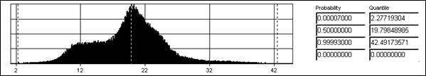
Fig.
3 Safety criterion – reaction
![]() (x
= 0 m)
(x
= 0 m)
Resulting values
calculated according to Eurocode and SBRA method are shown in Tab. 3.
From the table is clearly, that in case of Eurocode the reaction
![]() reach
negative values, thus the reliability condition (5) is not met. Thus,
the beam must be fixed using suitable anchor. In case of the
calculation according to SBRA method, the reliability criterion Pf
< Pd is met, thus the beam is safe from
the viewpoint of stability of position.
reach
negative values, thus the reliability condition (5) is not met. Thus,
the beam must be fixed using suitable anchor. In case of the
calculation according to SBRA method, the reliability criterion Pf
< Pd is met, thus the beam is safe from
the viewpoint of stability of position.
Tab. 3 Reliability assessment – static equilibrium
The following safety criterion regards to failure due to shear force.
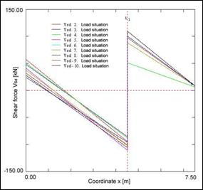
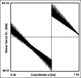
Fig. 4 Shear forces along the beam – calculation according to Eurocode and SBRA Metod
Reliability assessment according to Eurocode is based on reliability criterion check:
![]() ,
(N) (7)
,
(N) (7)
where VSd
is design load effect (shear force) and
![]() is
design plastic strength in shear:
is
design plastic strength in shear:
![]() ,
(N) (8)
,
(N) (8)
where
![]() is
shear area,
is
shear area,
![]() is
steel yield stress and
is
steel yield stress and
![]() is
partial reliability factor (see [7]). Determination of critical load
effects is based on finding of critical load situations using
combination formula (6.10) [5]. Alternatively can be used more
precise approach using combination formulas (6.10a and 6.10b) [5].
Critical load situations 2-10 corresponding to these combination
formulas are shown in Tab. 4. These critical load situations were
used for shear forces calculation. The resulting developments of
these shear forces along the beam are shown in Fig. 4 on the left.
From this figure is clearly, that extremes of shear forces are close
to the left and to the right of the support (b) – see Fig. 1.
In these points is necessary to perform the reliability assessment
according to criterion (7).
is
partial reliability factor (see [7]). Determination of critical load
effects is based on finding of critical load situations using
combination formula (6.10) [5]. Alternatively can be used more
precise approach using combination formulas (6.10a and 6.10b) [5].
Critical load situations 2-10 corresponding to these combination
formulas are shown in Tab. 4. These critical load situations were
used for shear forces calculation. The resulting developments of
these shear forces along the beam are shown in Fig. 4 on the left.
From this figure is clearly, that extremes of shear forces are close
to the left and to the right of the support (b) – see Fig. 1.
In these points is necessary to perform the reliability assessment
according to criterion (7).
Tab. 4 Critical load situations and corresponding reliability partial factors
Reliability assessment according to SBRA method is based on reliability criterion check:
![]() ,
(-) (9)
,
(-) (9)
where
![]() is
target probability of failure and
is
target probability of failure and
![]() is
probability of failure calculated from reliability function:
is
probability of failure calculated from reliability function:
![]() ,
(N) (10)
,
(N) (10)
where
![]() is
load effect (shear force). Elastic shear strength
is
load effect (shear force). Elastic shear strength
![]() is
calculated according to the equation (see [9]):
is
calculated according to the equation (see [9]):
 ,
(N) (11)
,
(N) (11)
where
![]() is
steel yield stress considered by bounded histogram „St235.dis“
(see Fig. 2),
is
steel yield stress considered by bounded histogram „St235.dis“
(see Fig. 2),
![]() is
moment of inertia,
is
moment of inertia,
![]() is
web width and
is
web width and
![]() is
static moment. Value 0,9 in formula (11) represents correction
expressing difference between measured value of steel yield stress
and real value of steel yield stress. For the following reliability
assessment is useful to determine the shear forces development along
the beam length. This shear forces development was calculated using
computer program AntHill for Windows (see Fig. 4 – on the
right). From this figure is clearly, that extremes of shear forces
are close to the left and to the right of the support (b) – see
Fig. 1. In these points is necessary to perform the reliability
assessment according to the criterion (9). The analysis of
reliability function (10) was performed in these points using
computer program AntHill for Windows (see Fig. 5 and Fig. 6). The
calculation corresponds to 100000 simulation steps.
is
static moment. Value 0,9 in formula (11) represents correction
expressing difference between measured value of steel yield stress
and real value of steel yield stress. For the following reliability
assessment is useful to determine the shear forces development along
the beam length. This shear forces development was calculated using
computer program AntHill for Windows (see Fig. 4 – on the
right). From this figure is clearly, that extremes of shear forces
are close to the left and to the right of the support (b) – see
Fig. 1. In these points is necessary to perform the reliability
assessment according to the criterion (9). The analysis of
reliability function (10) was performed in these points using
computer program AntHill for Windows (see Fig. 5 and Fig. 6). The
calculation corresponds to 100000 simulation steps.
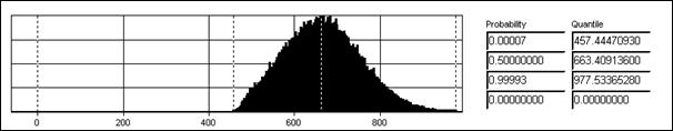
Fig. 5 Shear reliability function RFV (x = 4,49999 m)
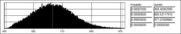
Fig. 6 Shear reliability function RFV (x = 4,50001 m)
Resulting values calculated according to Eurocode and SBRA method are shown in Tab. 5. From the table is clearly, that the calculations according to Eurocode and SBRA lead to reliability criterion (7) and (9) meeting. However, in case of Eurocode approach the resistance is related to plastic strength, while in case of SBRA approach the resistance is related to steel yield stress.
Tab. 5 Reliability assessment – shear
In the following is performed the reliability assessment from the viewpoint of bending.
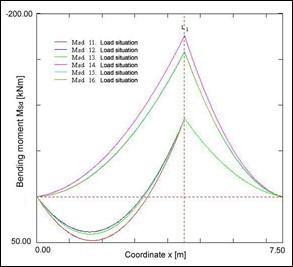
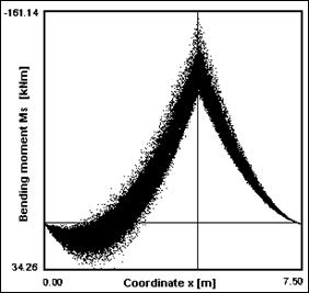
Fig. 7 Bending moments along the beam – calculation according to Eurocode and SBRA Metod
Reliability assessment according to Eurocode is based on reliability criterion check:
![]() ,
(N.m) (12)
,
(N.m) (12)
where
![]() is
design load effect (bending moment) and
is
design load effect (bending moment) and
![]() is
design plastic bending resistance given by equation:
is
design plastic bending resistance given by equation:
![]() ,
(N.m) (13)
,
(N.m) (13)
where
![]() is
plastic cross-secion modulus,
is
plastic cross-secion modulus,
![]() is
steel yield stress and
is
steel yield stress and
![]() is
partial reliability factor (see [7]).
is
partial reliability factor (see [7]).
Determination of critical load effects is based on finding of critical load situations using combination formula (6.10) [5]. Alternatively can be used more precise approach using combination formulas (6.10a and 6.10b) [5]. Critical load situations 11-16 corresponding to these combination formulas are shown in Tab. 6. These critical load situations were used for bending forces calculation (see Fig. 7 on the left). From this figure is clearly, that extreme of bending moments is in support (b). In this point is in the following performed the reliability assessment according to the criterion (12).
Tab. 6 Critical load situations and corresponding partial reliability factors
Reliability assessment according to SBRA method is based on reliability criterion check:
![]() ,
(-) (14)
,
(-) (14)
where
![]() is
target probability of failure and
is
target probability of failure and
![]() is
resulting probability of failure calculated from reliability
function:
is
resulting probability of failure calculated from reliability
function:
![]() ,
(N.m) (15)
,
(N.m) (15)
where MS
is load effect (bending moment) and
![]() is
elastic bending reistance:
is
elastic bending reistance:
![]() ,
(N.m) (16)
,
(N.m) (16)
where
![]() is
elastic cross-section modulus and
is
elastic cross-section modulus and
![]() is
steel yield stress represented by bounded histogram „St235.dis“
(see Fig. 2). Value 0,9 in formula (16) represents correction
expressing difference between measured value of steel yield stress
and real value of steel yield stress. For the reliability assessment
is useful to determine the bending moments development along the beam
length. This bending moments development was calculated using
computer program AntHill for Windows (see Fig. 7 on the right). From
this figure is clearly, that extreme of bending moments is in support
(b) – see Fig. 1. In this points is necessary to perform the
reliability assessment according to criterion (14). The analysis of
reliability function (15) was performed in this points using computer
program AntHill for Windows (see Fig. 8). The calculation corresponds
to 100000 simulation steps.
is
steel yield stress represented by bounded histogram „St235.dis“
(see Fig. 2). Value 0,9 in formula (16) represents correction
expressing difference between measured value of steel yield stress
and real value of steel yield stress. For the reliability assessment
is useful to determine the bending moments development along the beam
length. This bending moments development was calculated using
computer program AntHill for Windows (see Fig. 7 on the right). From
this figure is clearly, that extreme of bending moments is in support
(b) – see Fig. 1. In this points is necessary to perform the
reliability assessment according to criterion (14). The analysis of
reliability function (15) was performed in this points using computer
program AntHill for Windows (see Fig. 8). The calculation corresponds
to 100000 simulation steps.
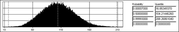
Fig. 8 Bending reliability function RFM (x = 4,5 m)
Resulting values calculated according to Eurocode and SBRA method are shown in Tab. 7. From the table is clearly, that calculation about both these methods leads to reliability condition (12) and (14) meeting. However, in case of Eurocode approach the resistance is related to plastic strength, while in case of SBRA approach the resistance is related to steel yield stress.
Tab. 7 Resulting values - bending
By the simplified calculation was proved, that combination of shear forces and bending moments do not decide about the failure of considered structure.
Serviceability criteria are in considered study related to vertical deflections due to live loads acting (chapter 10) and vertical deflections due to all loads acting (chapter 11).
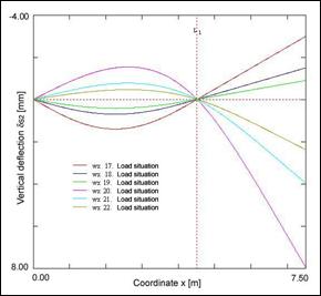
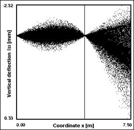
Fig. 9 Vertical deflections of the beam due to live loads acting – calculation according to Eurocode and SBRA Metod
Reliability assessment according to Eurocode is based on reliability criterion check:
![]() ,
(m) (17)
,
(m) (17)
where
![]() is
load effect (vertical deflection of the structure due to live loads
acting) and
is
load effect (vertical deflection of the structure due to live loads
acting) and
![]() is
limiting vertical deflection (investor‘s requirment) given by
equation:
is
limiting vertical deflection (investor‘s requirment) given by
equation:
![]() (m) (18)
(m) (18)
The maximum load effect determination is based on critical load situations analysis using combination formulas (6.14b), (6.15b), (6.17b) [5]. The critical load situations 17-22 corresponding to these combination formulas are shown in Tab. 8. From these critical load situations were calculated vertical deflections of the beam due to live loads acting (see Fig. 9 on the left). From this figure is clearly, that the extremas are in points c and d (see Fig. 1). In these points is necessary to perform reliability assessment according to reliability criterion (17).
Tab. 8 Critical load situations and corresponding reliability partial factors
Reliability assessment according to SBRA method is based on reliability criterion check:
![]() ,
(-) (19)
,
(-) (19)
where
![]() is
target probability of failure and
is
target probability of failure and
![]() is
probability of failure calculated from reliability function:
is
probability of failure calculated from reliability function:
![]() ,
(m) (20)
,
(m) (20)
where
![]() is
live load effect (vertical deflection due to live loads acting) and
is
live load effect (vertical deflection due to live loads acting) and
![]() is
limiting vertical deflection (investor’s requirement) given by
equation:
is
limiting vertical deflection (investor’s requirement) given by
equation:
![]() ,
(m) (21)
,
(m) (21)
Using computer program AntHill for Windows were calculated vertical deflections of the beam due to live loads acting (see Fig. 9 on the right). From this figure is clearly, that the extremas are in points c and d (see Fig. 1). In these points is necessary to perform reliability assessment according to reliability criterion (19). The analysis of corresponding reliability functions for both points d and c is shown in Fig. 10 and Fig. 11. The calculation corresponds to 100000 simulation steps.
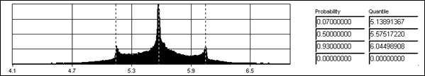
Fig. 10 Reliability function of vertical deflections RFd,2 (x = 2,6 m)
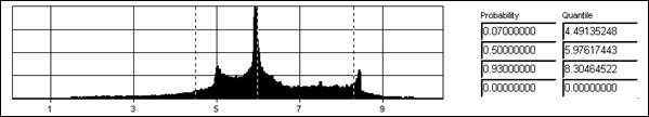
Fig. 11 Reliability function of vertical deflections RFd,2 (x = 7,5 m)
Resulting values calculated according to Eurocode and SBRA method are shown in Tab. 9. From this table is clearly, that in case of Eurocode is not met the reliability criterion (17) in point d. In case of SBRA method the reliability criterion (19) is met in both points – c and d.
Tab. 9 Resulting values – vertical deflections due to live loads acting
In the following calculation the vertical deflections due to all loads acting are assessed.
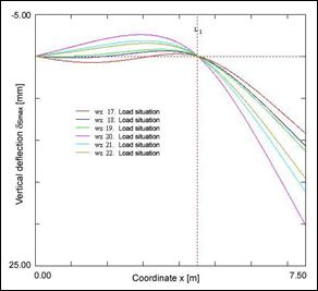
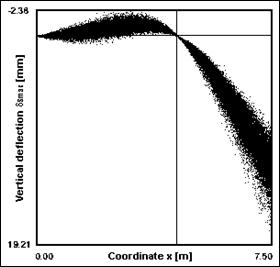
Fig. 12 Vertical deflection of the beam due to all loads acting – calculation according to Eurocode and SBRA method
Reliability assessment according to Eurocode is based on reliabilty criterion check:
![]() ,
(m) (22)
,
(m) (22)
where
![]() is
load effect (vertical deflection due to all loads acting) and
is
load effect (vertical deflection due to all loads acting) and
![]() is
limiting vertical deflection (investor’s requirement) given by
equation:
is
limiting vertical deflection (investor’s requirement) given by
equation:
![]() (m) (23)
(m) (23)
The maximum load effect determination is based on critical load situations analysis using combination formulas (6.14b), (6.15b), (6.17b) [5]. The critical load situations 17-22 corresponding to these combination formulas are shown in Tab. 10. From these critical load situations were calculated vertical deflections of the beam due to all loads acting (see Fig. 12 on the left). From this figure is clearly, that the extremas are in points c and d (see Fig. 1). In these points is necessary to perform reliability assessment according to reliability criterion (22).
Tab. 10 Critical load situations and corresponding reliability partial factors
Reliability assessment according to SBRA method is based on reliability criterion check:
![]() ,
(-) (24)
,
(-) (24)
where
![]() is
target probability of failure and
is
target probability of failure and
![]() is
probability of failure calculated from reliability function:
is
probability of failure calculated from reliability function:
![]() ,
(m) (25)
,
(m) (25)
where
![]() is
load effect (vertical deflection due to all loads acting) and
is
load effect (vertical deflection due to all loads acting) and
![]() is
limiting vertical deflection (investor’s requirement) given by
equation:
is
limiting vertical deflection (investor’s requirement) given by
equation:
![]() (m) (26)
(m) (26)
Using computer program AntHill for Windows were calculated vertical deflections of the beam due to all loads acting (see Fig. 12 on the right). From this figure is clearly, that the extremas are in points c and d (see Fig. 1). In these points is necessary to perform reliability assessment according to reliability criterion (24). The analysis of corresponding reliability functions for both points d and c is shown in Fig. 10 and Fig. 11. The calculation corresponds to 100000 simulation steps.
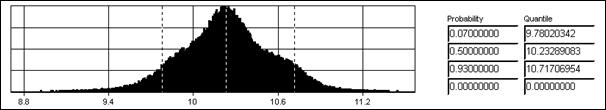
Fig. 13 Reliability function of vertical deflections RFd,max (x = 2,9 m)
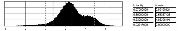
Fig. 14 Reliability function of vertical deflections RFd,max (x = 7,5 m)
Resulting values calculated according to Eurocode and SBRA method are shown in Tab. 11. From this table is clearly, that in case of Eurocode is not met the reliability criterion (22) in point d. In case of SBRA method the reliability criterion (24) is met in both points – c and d.
Tab. 11 Resulting values – vertical deflections due to all loads acting
On simply example of the steel beam with overhanging end were demonstrated the differences between approach based on „prescriptive“ interpretation of „Partial Factor Design“ and fully probabilistic approach represented by SBRA method. It is difficult to compare these two approaches, due to evidently different applied procedures. The approach according to SBRA method allow to consistently analyse all possible interactions of all input quantities, which can be considered as random variable. This approach leads to determination of real reliability of considered structure and to achievement of non-negligible cost savings.
The support of the Grant Agency of the Czech Republic (Projects No. 103/01/1410 and 105/01/0783) is gratefully acknowledged.
[1] Marek, P., Guštar, M., Anagnos, T.: Simulation-Based Reliability Assessment for Structural Engineers. CRC Press Inc., Boca Raton, Florida, 1995.
[2] Marek, P., Guštar, M. a Bathon, L.: Tragwerksbemessung. Von deterministischen zu probabilistischen Verfahren. Academia, Praha 1998.
[3] Marek, P., Brozzetti, J., Guštar, M.: Probabilistic Assessment of Structures using Monte Carlo Simulation. Background, Exercises and Software. Institut of Theoretical and Applied Mechanics, Academy of Sciences of the Czech Republic, Praha, 2001.
[4] Del Corso, R., Gulvanessian, H., Holický, M., Marková, J., Steenbergen, H., Vrouwenvelder, T.: Navrhování konstrukcí podle nových Evropských předpisů – podle Eurokódů. Sborník přednášek a řešených příkladů. KÚ ČVUT, Praha, 2000, ISBN 80-01-02263-3.
[5] EN 1990: Basis of Desing. European Comittee for Standardisation. CEN/TC250, working draft, July 2000.
[6] ČSN P ENV 1991-1-1: Zásady navrhování a zatížení konstrukcí. Část 1: Zásady navrhování. Český normalizační institut, Praha, 1996.
[7] ČSN P ENV 1993-1-1: Navrhování ocelových konstrukcí. Část 1.1: Obecná pravidla a pravidla pro pozemní stavby. Český normalizační institut, Praha, 1994.
[8] ČSN 73 1401: Navrhování ocelových konstrukcí. Český normalizační institut, Praha, 1998.
[9] Šmiřák, S.: Pružnost a plasticita I pro distanční studium. Akademické nakladatelství CERM, s.r.o. Brno, 1999, ISBN 80-214-1151-1.
[10] Kadlčák, J. a kol.: Statika stavebních konstrukcí I. VUT Brno, nakladatelství VUTIUM, 1998, ISBN 80-214-1204-6.
[11] Pustka, D., Disertation work: Využití spolehlivostní metody SBRA při navrhování ocelových, betonových a ocelobetonových konstrukcí. VŠB – Technical University of Ostrava, Ostrava, September 2002.